Differential Cage
The 2019-2020 CSUN FSAE Drivetrain/Machining Sub-Team decided to make a differential design change to increase tuning and serviceability. Other changes to the vehicle also changed the position of the drivetrain system which had to be acknowledged in the design of the Differential Cage (Diff. Cage). To accommodate a larger differential but keep the same compact packaging of the previous design (2018-2019 design) without failure, extensive research had to be done.
Research began with report gathering from previous teams at CSUN and several other schools. The main lesson that was gathered, is the fact that many people overlook the importance of this “simple” assembly and forget about the impact forces that deeply effect the cycle life. Familiarizing myself with the boundary conditions of the system, a Factor of Safety (FOS) was set to account for impact loading. Running several Finite Element Analyses (FEA) became mathematical evidence when comparing the results to the reported successes and failures of previous design iterations. Once all the weaknesses and strengths were found, the final product could be designed and tested [Right].
My 2020 Design for the Differential Cage Assembly (Including Differential and Bearings)
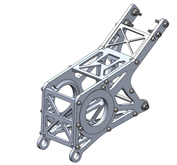
2018 Design A : Mounted both the engine and Drivetrain to the car.
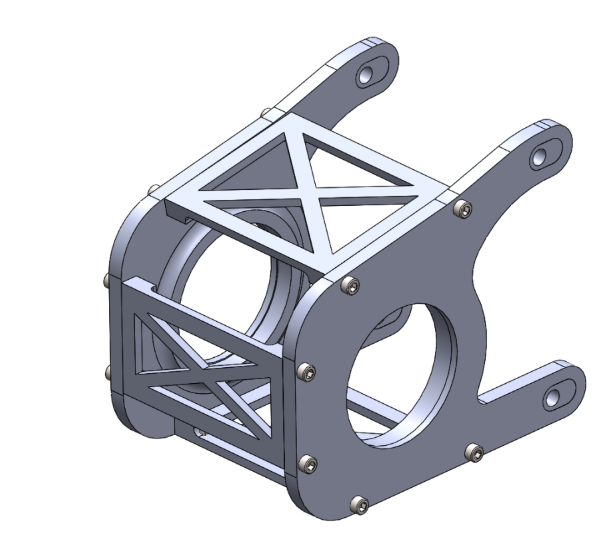
2018 Design B : Final Design for 2018. Due to an engine change, mounting conditions changed. Quick and large changes left sharp edges for manufacturing that led to crack propagations and eventually part failure. FEA done in 2020 confirmed cause of failure.
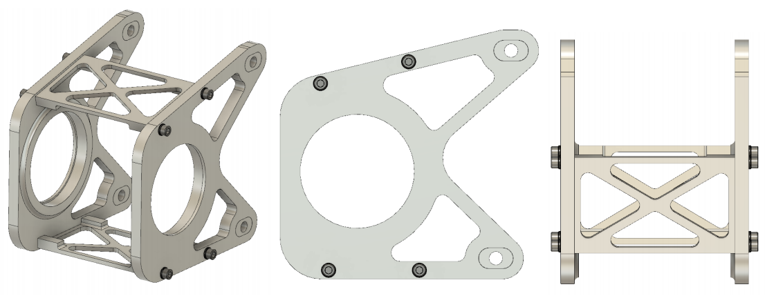
2019 Design : Featured an impressive weight reduction to the system and a simplified design. FEA confirms success of design and suggests areas to reduce even more weight.
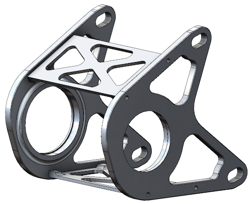
2020 Design : Design accommodates a much larger differential without sacrifice to weight reduction or strength.
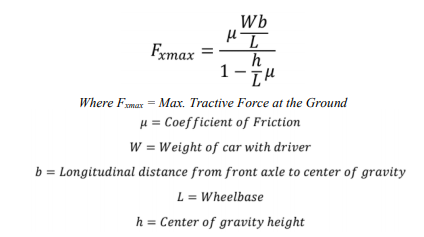
Finding the Boundary Conditions (1) : The Max Tractive Force generated from the tires will be experienced during straight-line acceleration from rest. Friction Coefficient is obtained from tire manufacturer and is confirmed with data acquisition.
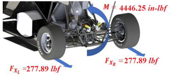
Finding the Boundary Conditions (2) : The Max Tractive Force is divided between the Drive Wheels as torque is distributed evenly amongst the two. The force in one tire is then multiplied by the radius of that tire to find the moment along the Rear Axle.
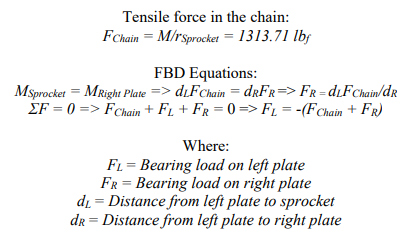
Finding the Boundary Conditions (3) : The moment is divided by the radius of the Rear Sprocket to obtain the tensile force in the Drive Chain. A Free Body Diagram is used to find the resulting force in each of the Diff. Cage Plates.
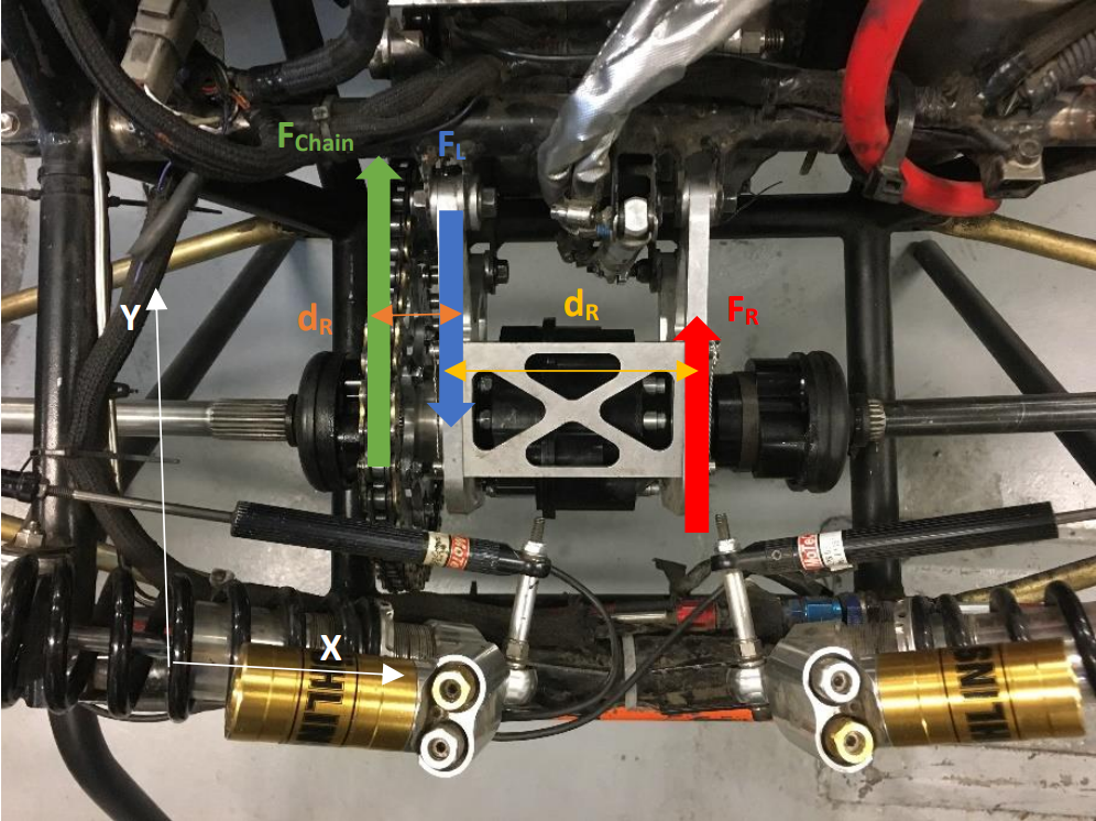
Free Body Diagram, determining the resultant forces.

Stress Results (2019 example) : Angle of the chain is found through the CAD Model of the full assembly of the car. A bearing force is applied with respects to the FBD resultants and fixtures are applied as necessary.
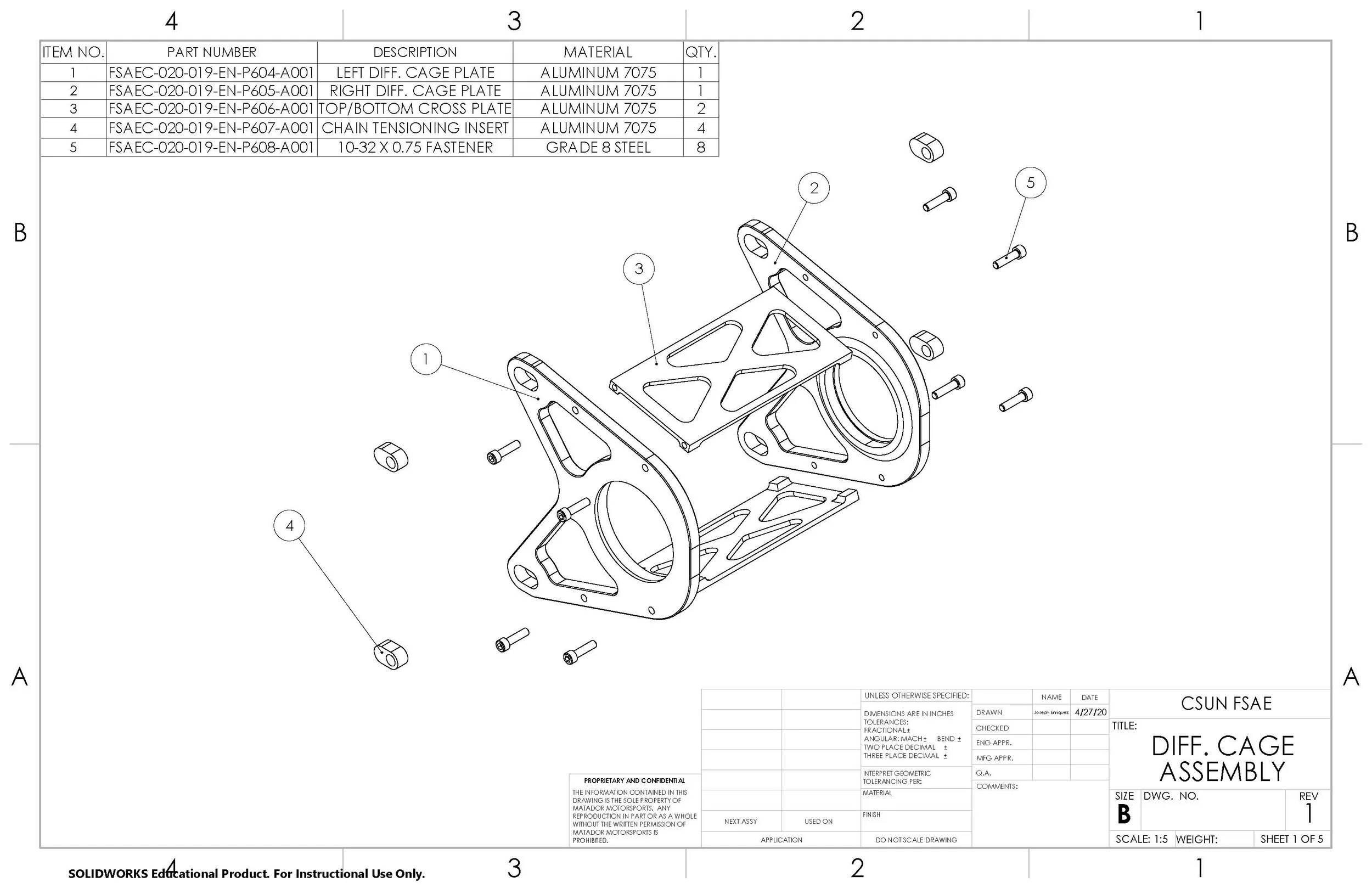
2020 Design: Assembly Explosion View: Left and Right Diff. Cage Plate, Top/Bottom Cross Plate, Chain Tensioning Insert, and Grade 8 Steel Fasteners.
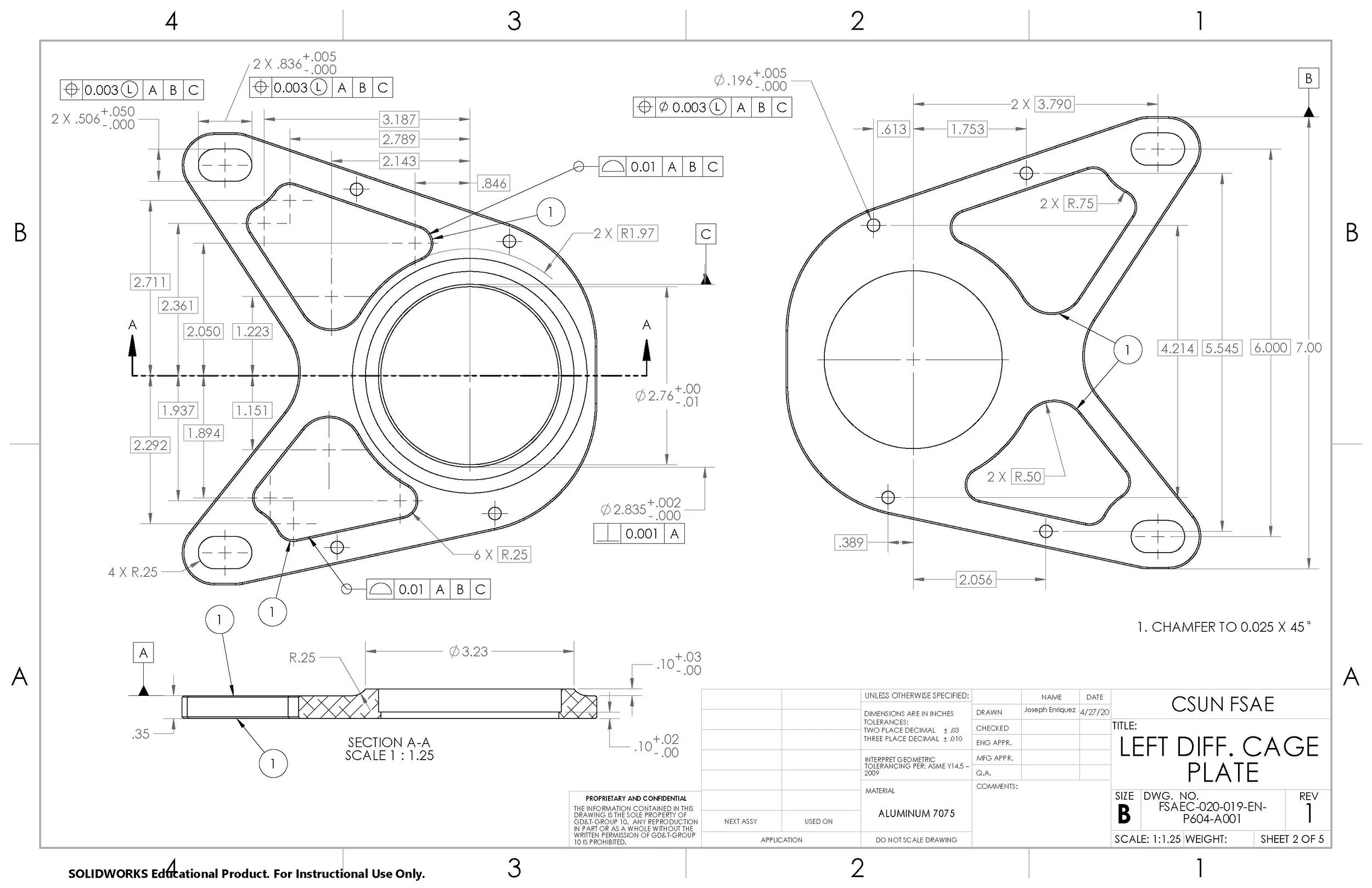
2020 Design: Left Diff. Cage Plate. Please Note: Right Diff. Cage Plate (Drawing Page 3 of 5) has been omitted to Save Space. Right Diff. Cage Plate only differences are mirrored features and a larger bearing Dimension.
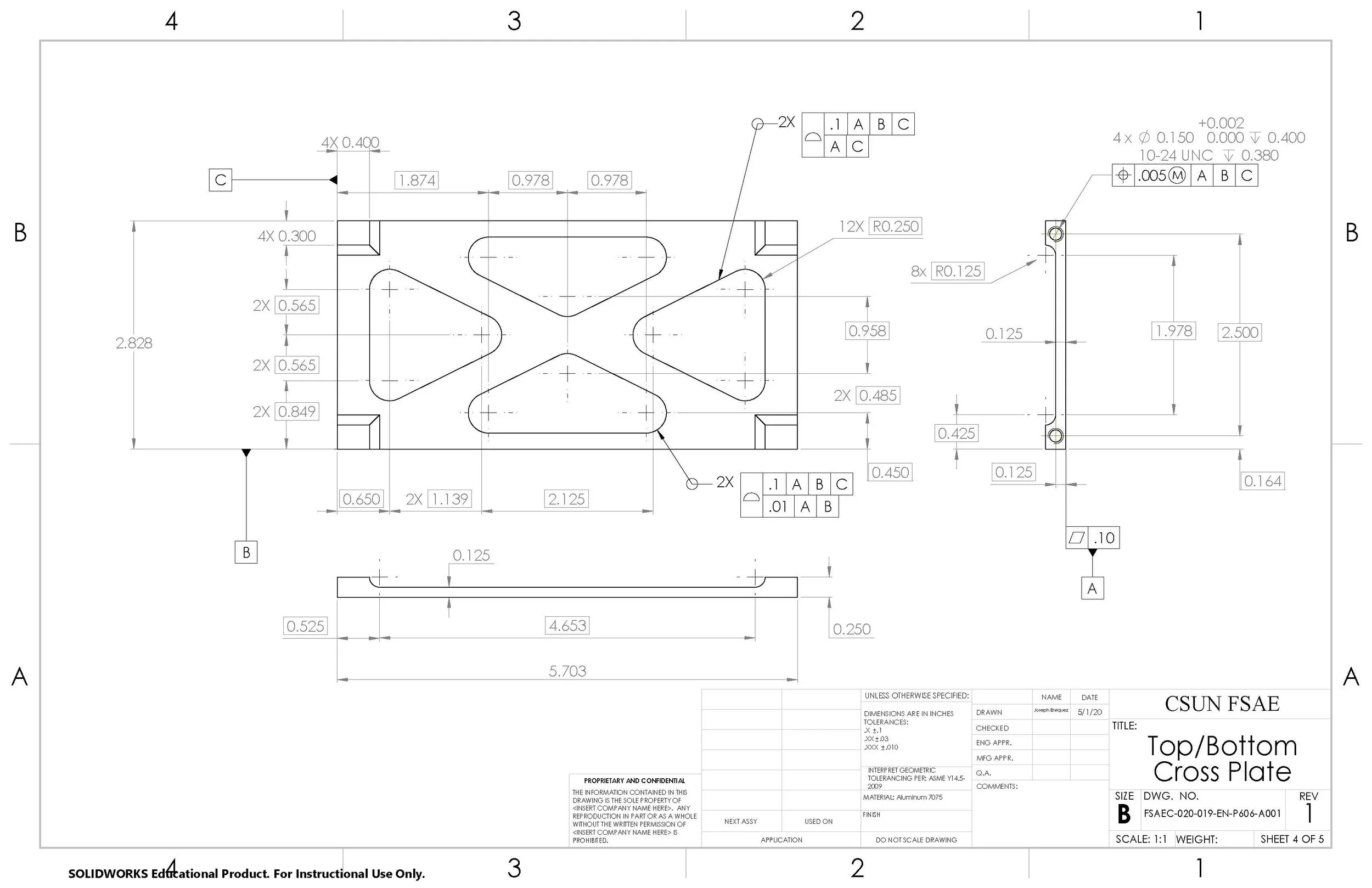
2020 Design: Top/Bottom Cross Plates are used to align the system and minimize vibrations and flexing during operation.
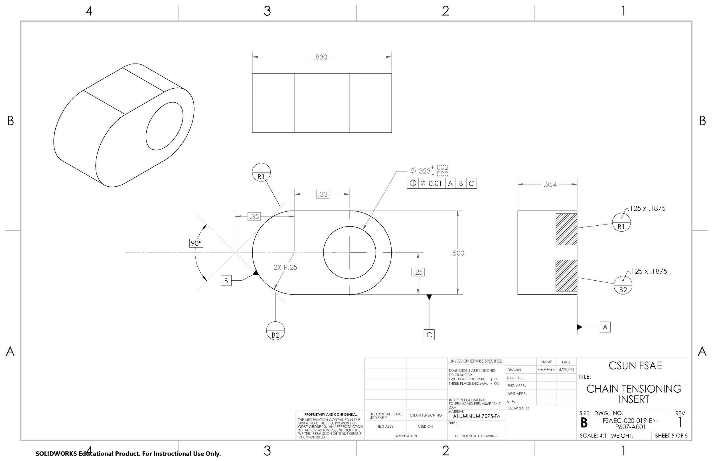
2020 Design: Chain Tensioning Inserts fit into the slots on the Left and Right Diff. Cage Plates. The holes provided by the Inserts mount the Diff. Cage Assembly to the chassis. But by manufacturing multiple Chain Tensioning Inserts with varying hole locations (Not Seen Here) provide adjustments for the Chain.
